

![]()
![]()
![]()
Appendix F - Breathing Air Systems for Use
with
Pressure-Demand Supplied Air Respirators
in Asbestos Abatement
| -DISCLAIMER- | This is not DOL or OSHA controlled material and is provided here for reference only. We take no responsibility for the views, content or accuracy of this information. |
a Technical Report
by
Clifton M. McClure
Consumer Fuels, Inc.
7250 Governors Drive West
Huntsville, Alabama 35805
for
U.S. Department of Health and
Human Services
Public Health Service
Centers for Disease Control
National Institute for Occupational Safety and Health
Division of Safety Research
ACKNOWLEDGEMENTS
The author is indebted to the following individuals who provided invaluable suggestions during the development of this Appendix:
William L. Bowers
Daboco, Inc.
3319 E. 10 Mile Rd.
Warren, MI 48091
Dorothy Rushton
Deltech Engineering, Inc.
Century Park, Box 667
New Castle, Delaware 19720
Table of Contents
I. Introduction
(a) Compression
(b) Purification
(c) Distribution
(2) Adequate Reserve Air or Escape Time
(3) Temperature Control of the Breathing Air
(4) Continuous Carbon Monoxide (CO) Monitor and Alarm
(1) The Low Pressure System
(2) The High Pressure System
(3) High Pressure Pre-Pumped Tanks
(4) Other
III. Cautions in the Use of Breathing Air Systems
IV. Cost Analysis: Supplied Air versus Air-Purifying Respirator Systems
V. Suppliers of Breathing Air Equipment
Figures and Tables
Figure
1.
Theoretical Air Compression
Figure 2. Typical Installation of Low Pressure Breathing Air
System
Figure 3. The Vortex Tube, its Construction and Performance
Figure 4. Typical Low Pressure Breathing Air Purifier
Assembly
Figure 5. Typical High Pressure Breathing Air System
Figure 6. Typical High Pressure Purifier Assembly
List of Tables
Table 1. Characteristics of Grade D and Better Breathing Air
Table 2. Typical Pressure and Relative Adsorber Effectiveness
Appendix F. Breathing Air
Systems for Use with
Pressure-Demand Supplied Air Respirators
in Asbestos Abatement
I. INTRODUCTION
The National Institute for Occupational Safety and Health (NIOSH) and the Environmental Protection Agency (EPA) recommend that either self-contained breathing apparatus (SCBA) or combination pressure-demand supplied air respirators (SAR) with escape SCBA be used to protect workers from detectable airborne concentrations of asbestos. Since SCBA are often impractical for abatement due to their size and weight, the combined SAR/SCBA will probably offer the best protection for workers on abatement jobs. Only those respirators tested and certified by NIOSH (U.S. Department of Health and Human Services) and the Mine Safety and Health Administration (MSHA, U.S. Department of Labor) and therefore which bear the NIOSH/MSHA approval label (See Appendix B) are recommended.
As the term "supplied air" indicates, these respirators receive breathable air from an external source through a system that typically consists of compression, purification, storage, and distribution components. The subject of this Appendix is the system which produces breathable air and supplies it to the recommended respirators. The intent is to (1) acquaint employers with the characteristics of available types of breathing air systems (Part II), (2) emphasize the caution required in the use of such systems (Part III), and (3) examine the cost benefits of supplied air versus air-purifying respirator systems (Part IV). The names and addresses of suppliers of equipment used in and with breathing air systems are provided in the final section (Part V).
A breathing air system must accomplish the following:
- provide a continuous sufficient supply of Grade D breathing air
- provide adequate reserve or escape time
- provide breathing air temperature control
- provide a continuous monitor and alarm against carbon monoxide (CO) in the breathing airstream.
(1) Continuous Sufficient Supply of Grade D Breathing Air
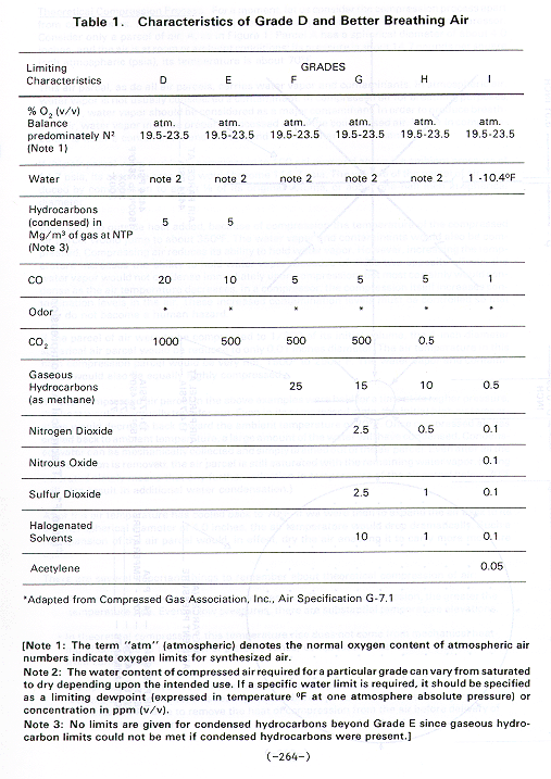
A continuous sufficient supply of breathing air means that both the air pressure and air volume requirements necessary for respirator operation are supplied directly to each respirator. Grade D breathing air is air that meets certain criteria established by the Compressed Gas Association, Inc., and is required to be used in air supplied respirators (see Table 1). Producing and supplying a continuous sufficient supply of Grade D breathing air is accomplished by the combined effect of compression, purification, and delivery processes.
(a) Compression
Any person interested in specification of, purchasing, or operation of any breathing air system for use with pressure-demand supplied air respirators in asbestos removal should know the basics of air compression.
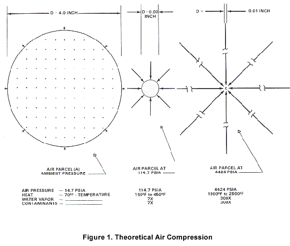
Theoretical Compression Process. For a moment, let us consider the compression process apart from compressors. Forget low or high pressure or any other type of mechanical compressor. Consider only a parcel of air, A, as in Figure 1. Parcel A has a spherical diameter of about 4.0 inches, and the air is at room or ambient conditions; its pressure is about 14.7 pounds per square inch atmospheric (psi); its temperature is about 70�F.
This air parcel, as do all air parcels, carries water vapor and contaminants. In atmospheric air, water vapor is not usually considered a contaminant. In compressed air for breathing purposes, however, water vapor should be considered as a major contaminant. In order to produce breathable air, water vapor must be properly processed out of the compressed air. Water in compressed air is itself a contaminant and it traps and carries other contaminants.
If this air parcel were suddenly compressed to 100 psi over and above it's ambient pressure of 14.7 psi, its absolute pressure would become 114.7 psi. The volume of the parcel of air is reduced by compression to about 1/8 of its original volume, or about one-half inch in spherical diameter.
Even with no outside heat added, because of compression the temperature of the compressed air parcel would jump to about 350�F. The water vapor and contaminants would also be compressed. Compressing air reduces its ability to hold water vapor. However, increasing the temperature increases the ability to hold water vapor. Because of these two opposite effects, the water vapor would not condense immediately upon compression, but most certainly would condense as the air temperature decreases. In a compressor, the compression itself increases contamination levels in the air. These increased contamination levels must be controlled so that they do not become a human hazard.
If the parcel of air were to be compressed to 1/300 of its initial volume, the 4-inch diameter spherical air parcel would be reduced to only 0.01 inches diameter. The air temperature in this high compression parcel would be very hot, 1500� to 2500�F. The water vapor and contaminants would also be equally highly compressed.
If either compressed air parcel in the above examples were held for a time at its higher pressure, the heat would eventually transfer out. Even in its compressed state, the initial high air temperature would decrease back toward the ambient temperature of 70�F. Once compressed air has cooled back to ambient temperature, a large amount of the water will have condensed. Condensed water can be mechanically collected and simply drained out of the air parcel. Even after all the condensation is removed, the air parcel is still saturated with the remaining water vapor. (Being saturated simply means that any further reduction in temperature of the air parcel below 70�F will also result in additional water condensation.)
After the air temperature has cooled back to 70�F, if we were then to expand the air back to its original spherical diameter of 4.0 inches, the air temperature would drop dramatically. Such a re-expansion of the air parcel would, in effect, dry the air, enabling it to carry more moisture again.
There are several important things to remember about theoretical compression of air:
- Air temperature always rises with compression. The more compression, the greater the temperature rise. Even at low pressures, there are substantial temperature elevations.
- In theoretical compression, this temperature rise does not come from mechanical heating effects due to the action of pistons, vanes, compressor drive motors, etc., but only from compression.
- Compression always heats air, but the compression process can be designed to provide cooling effects in the air. This cooling is available only if sufficient heat exchanger design and time is available to remove the heat of compression from the air before delivery of the air to the workers.
- The water vapor is also compressed, and if high temperatures are lowered, will easily condense.
- Water vapor in compressed air is a major contaminant. Condensed water in compressed air is itself a contaminant and it traps and carries other contaminants.
- Concentrations of contaminants are increased and may become hazardous unless removed.
Figure 1. Theoretical Air Compression
Table 1. Characteristics of Grade D and Better Breathing Air.
Practical Compression. Real compression requires a mechanical compressor of some type. Additional heat from the drive motor and frictional heat will be added in the real compression process. In addition, the compressor will add wear particles such as metal, carbon, etc. The compressor may also add lubricant oil as either liquid oil or oil vapor. If the compressor operates at excessive temperatures, it may actually form deadly carbon monoxide (CO) within the machine, although such CO formation is rare.
A compressor may be suited for only the tasks or types of jobs for which it was originally designed and built. For instance, a compressor built to power other industrial air machines may not need heat, water, and oil removal. In fact, some compressors actually have "oilers'' in the output air to increase the oil being carried in the air. A compressor whose basic design was unsuitable could easily overpower the finest air purifier assembly. Operating with such an unsuitable machine would require more frequent filter and canister replacement than normal to maintain the required air quality. The cost of maintaining the air purifier in such a case would be prohibitive. The cost of redesigning and re-building such a compressor could be more than buying a compressor of a different design.
The real effect of water as a contaminant can be understood with an example: Consider a low pressure breathing air system with a normal piston or screw-type compressor and an air purifier assembly, such as depicted in Figure 1. This actual machine is pumping 100 standard cubic feet per minute (SCFM) of air on a day when the ambient temperature is 70�F and the relative humidity is 75%. This machine will take in about 16.5 gallons of water in vapor form every 24 hours. If the machine is properly designed for breathing air applications, it will have an aftercooler to cool the air and to condense most of this water. This breathing air compressor will also have water removal traps to drain the condensate out of the machine. If the air is being cooled in the compressor aftercooler back to near ambient temperature, then about 11.5 gallons of liquid water will condense. This condensing water has many of the other contaminants entrained. This contaminated liquid water can be mechanically removed from the aftercooler drain trap. This leaves about 5.0 gallons of water as water vapor still moving with the compressor output air. Most of this 5.0 gallons of water vapor will be removed along with any other contaminants by the air purifier assembly that is downstream of the compressor.
Proper design of the compressor with sufficient intercooling, aftercooling, and proper water removal traps can mechanically remove about 65% to 90% of all water and contaminants. Since mechanical removal methods are more or less permanent removal methods, the overall compressor design is important for final breathing air quality. The final polishing of the air quality to obtain Grade D or better will be accomplished by stages in the air purifier assembly.
(b) Purification
Ordinary compressed air cannot be used to supply breathing air to work crews working in hazardous atmospheres. Ambient breathing air, when pumped through an ordinary compressor, is not fit for human respiration. Even if the compressed air is filtered to remove dust and other particulates, it still contains the contaminants in ordinary atmospheric air, plus the localized contaminants near the compressor intake, plus any contaminants and wear particles added during compression. The compressor may add oil vapor, hydrocarbons, even carbon monoxide.
The compressor intake is especially vulnerable to all types of carbon monoxide sources. Sources of CO, such as transient vehicles and other mobile internal combustion engines, are especially hard to control on the typical asbestos abatement job.
Various contaminants are potentially present in air from ordinary compression. Where present, these contaminants are concentrated by the compression process. For these reasons, breathing apparatus will NOT provide protection unless the breathing air is purified.
Purification of air is a very precise technology which has developed over many years. Purification is considerably more than filtration. Filtration is simply capture and removal of particulates by a filter. Filtration is almost always included in the overall purification process, although it is a small part of the overall purifying process.
Adsorption. Purifiers are based primarily on the design and use of ADSORPTION. Adsorption of vapor and chemical contaminants is done by proper design and use of the class of materials known as absorbers. The common absorbers used in design of air purifier assemblies may include:
molecular sieves
silica gel
activated alumina (Al2O3)
activated charcoal
Adsorbers are porous type materials with large quantities of interconnected, submicroscopic internal voids, pores, or capillaries. This internal porous structure gives these adsorber materials very large surface areas in contact with the gases to which the adsorber is exposed. Adsorbers also have the property of being physiochemically "active" or can be ''activated." This means that these absorbers can hold onto, or adsorb onto their active surfaces, various physiologically active contaminants. The adsorbent thereby effectively removes the contaminants from the airstream and leaves the air pure and uncontaminated. These absorbers are not all equally effective with all contaminants.
Water is an active contaminant for most absorbers. Water is also processed in large quantities by air compression. Ninety percent of the water and entrained contaminants can regularly be removed by proper compression, cooling, and water traps, all of which are designed into the breathing air compressor section. Much of the remaining water must still be removed in order to allow adsorption of other vapor contaminants.
For the adsorber design to be effective, the appropriate types, quantities, and sequence of adsorber materials must be selected.
Pressure Level and Adsorbers. The effectiveness of all absorbers increases with increasing pressure. As the pressure of the air increases, the density of the air increases. More dense air exposed to any adsorber material simply means that more of the air is pushed into more intimate contact within the adsorber. Therefore, as air pressure increases, less adsorber is needed to do the same job.
Table 2 shows the typical operating pressure range and the relative density increase for both typical types of breathing air systems for use in asbestos removal work.
Table 2. Typical Pressure and Relative Adsorber Effectiveness
Adsorbers must be periodically replaced. Adsorber cartridges can be equipped with a color change reaction that will show the progress of adsorber use. Such cartridges can be changed based on coloration changes through a visual canister. Adsorption canisters may also be changed on a simple operational time basis.
The Carbon Monoxide Catalyst. The action of this catalyst which is used to eliminate carbon monoxide, is unique. On the catalyst surface, carbon monoxide, in the low concentration ranges of 10 ppm to 600 ppm, is brought into contact with oxygen in the air. These conditions cause the chemical reaction 2CO + O2 = 2 CO2. The end result is that dangerous CO is changed to CO2 which is not harmful in these low concentrations. Theoretically, catalysts last forever, but in practice they permanently adsorb trace chemicals and become ''inactive." Most manufacturers recommend yearly replacement of their catalyst-type filters.
Even very small amounts of water vapor contamination on the catalytic adsorber ''poison" the catalyst and reduce its activity. For such a catalyst to operate for a reasonable period of time, the air entering the catalyst must be very dry, below 5% relative humidity.
The most effective way to dry air to these conditions is to use drying absorbents before the air reaches the catalyst. If a drying adsorber of the throwaway type were considered for use in a low pressure purifier assembly, enormous quantities of this disposable adsorber material would be required for each 8-hour shift. In order to avoid having to use such quantities of water adsorber material in the low pressure purifiers, a different design solution has been used.
The Regenerative Water Adsorber Dryer. The heatless air regenerated dryer has evolved as the simplest and most rugged method to continuously regenerate the required adsorber material. It consists of airline plumbing, two central air dryer towers, and a tower switching system. In action, this system has one tower drying the process airstream while the other tower is ''off cycle.'' From 10% to 20% of the dry air output of the ''on-cycle" tower (depending on system operating pressure) is split off and sent back down in reverse through the "off-cycle" tower. This regeneration air removes the water previously adsorbed in the ''off-cycle" tower and is vented to the atmosphere. In this way the off-cycle adsorber material is renewed or regenerated. Every few minutes on a regular basis, the cycle switches, alternating between the two towers.
A typical adsorber design for 100 SCFM process air flow, which has 50 pounds of activated alumina in each tower, can be expected to run regeneratively for several years before this activated alumina stops being regenerated. Replacement of 100 pounds of activated alumina only one time every 5 to 7 years is inexpensive. In comparison, a single column of activated alumina in a throwaway canister design would need about 100 pounds of new activated alumina every 8 hours.
If the activated alumina regenerated dryer were the first step in the purifying process just following the breathing air compressor, it would ''ace'' significant amounts of oil and oil vapor as well as water vapor. The regenerative dryer is based on the alternate adsorption and desorption of water from the adsorber. In these cycling towers oil will not desorb. The regenerative dryer will operate only a few days if no oil adsorption media is placed in front of the regenerative drying section. An oil adsorption prefilter must precede the dryer towers.
The Oil Adsorption Prefilter. The active media in the oil adsorption prefilter is chosen for its ability to selectively retain oil and oil vapor. It can be formulated with a color change reaction and placed into a visual canister for visual determination of the filter media remaining. The oil vapor adsorption prefilter may quickly be saturated if ''slugs'' of oil and water come from the compressor. Removal of liquid "slugs'' just prior to the oil prefilter is accomplished by the coalescing filter and drain trap.
The Coalescing Filter and Drain Trap. Compressors used for breathing air need great attention paid to removal of heat, which causes condensed liquids to be formed. These breathing air machines also provide special liquid removal devices called "liquid traps." Liquids are retained in the traps and can be drained from them.
Heat exchangers and drain traps do not remove vapors. Water vapor and oil vapor move through liquid traps. Also, microscopic drops of both liquid water and liquid oil (aerosols) act similar to vapor and move through ordinary liquid traps. The coalescing element is designed to cause these aerosols to impact on a myriad of mechanical elements within the coalescing filter. This action makes big drops out of the aerosols so they can be removed.
Summary of Important Points About Adsorption Purification:
- Purification of air requires adsorption as well as filtration.
- Purification and adsorber design is a highly developed science. Proper design of adsorber must include:
- proper choice of adsorber material
- sufficient quantities of adsorber
- proper sequencing of the correct absorbers.
- All absorbers must be changed periodically.
- Systems with higher working pressures will require less adsorber material to do the same job.
- A low pressure adsorber should include a regenerative dryer or enormous quantities of adsorber material will need to be replaced every eight (8) hours.
Grade D breathing air is specified by OSHA 29 CFR 1910.1 34(d)(1 ) as that listed by the Compressed Gas Association Specification G-7. 1. Table 1 shows the criteria for Grade D and better breathing air. Most established American manufacturers of both high and low pressure breathing air purifying systems design and test their systems to produce Grade D or better breathing air.
(c) Distribution
Breathing air must be delivered to the respirators in a continuous and sufficient supply, which means that both air pressure and air volume requirements must be maintained through the purification and delivery processes. Required air pressure can be ensured:
- by measuring and controlling the air pressure within the air delivery system at the entrance to the respirator hoses (Air pressure is adjusted to the required pressure specified by the manufacturer for each respirator.)
- by maintaining the required pressure under all flow conditions when all the respirators are being used.
Two factors which affect the respirator pressure during air flow are (1) the inside diameters of hoses and their connectors, and (2) the overall length of air supply hose. Respirator hose-line pressures must typically be maintained in the 65-100 pounds per square inch gauge (psig) range. The Occupational Safety and Health Administration (OSHA) and NIOSH regulations prohibit the actual hose length from the respirator manifold to exceed 300 feet in length.
In order to add low pressure supply hose beyond 300 feet, the respirator input pressure should be maintained at the required and specified value for the respirators being used. Extra large diameter supply hose from the compressor to the respirator hose manifold may allow some length increases beyond the 300 feet. The simplest method to add some extra length to the low pressure supply line is to provide a compressor with output pressure higher than the pressure required by the respirators, and to provide a regulator at the respirator manifold. This regulator functions to reduce, control, and maintain the correct respirator pressure at the inlet to the respirator hoses. An accurate pressure gauge should be located at the inlet to the respirator hoses. For increases in hose length to be acceptable, this respirator inlet pressure gauge must read the correct and required value specified for the respirators being used when under maximum flow conditions (i.e., with all available respirators in use).
An easy test of the low pressure distribution system can be conducted by:
- laying out the required length of air transfer hoses
- connecting all respirator manifolds
- attaching the maximum number of respirator hoses and respirators to be used (up to 300 feet if needed)
- pressurizing the system
- with all respirators in use, then check the pressure at the respirator manifolds.
Should the pressure at the manifolds be less than the specified respirator pressure, increasing the pressure may be accomplished by using extra-large diameter supply hoses, or increasing compressor pressure combined with use of a control regulator at the respirator manifolds. If one of these methods will allow the required respirator pressure to be maintained, the extra length is acceptable for use. If the required respirator pressure cannot be maintained, the hose lengths must be shortened until the specified respirator hose pressure can be maintained.
Remember: providing a continuous and sufficient supply of breathing air is accomplished by maintaining the correct and specified respirator inlet air pressure under all airflow conditions.
(2) Adequate Reserve Air or Escape Time
Providing for adequate reserve air or escape time is a necessary and required function of the breathing air system. The OSHA Safety and Health Manual 29 CFR 1910.134(d)(2)(ii) states: "A receiver of sufficient capacity to enable the respirator wearer to escape from a contaminated atmosphere in event of compressor failure and alarms to indicate compressor failure shall be installed in the system."
This poses the question of how much reserve time, and therefore how much stored air, is necessary. If a work crew were told an escape test was going to be conducted at a specified time, such a test might show that only 10 to 20 minutes were required. The escape time required under actual workplace conditions could be considerably longer. Complex airline routing and even tangling, work on scaffolding or in restricted access areas, and the requirement for the entire work crew to take showers can all lengthen escape time. For a crew size of ten workers, actual egress times have been measured at 30 to 50 minutes and more. Therefore, for most asbestos jobs a reserve time specification of 50 minutes to one hour is needed. Certain special asbestos jobs with more complicated egress conditions may need escape time of more than one hour.
Prepumped air or air stored in a pressure container is used as the method to obtain the requires escape time. However, it should be noted here that low pressure systems, with pressures up to 200 psi, are not capable of storing any appreciable escape time in any practical tank volume size. However, high pressure air storage in the2000 psi to4000 psi range is easily capable of meeting the required escape time and more. When high pressure tanks are used to provide one hour and more escape time, the overall tank size, weight and cost are within practical limits.
The requirement to use high pressure(2000to4000psi)astheonlypractical reserve air storage method does not adversely affect specification, choice, or the use of low pressure breathing air systems. The cost for providing a high-pressure standby reserve system with Grade D air on a low pressure breathing air system is minimal. The high pressure breathing air tanks for this standby air reserve do not need to be purchased; rental is the normal arrangement for suppliers of such high pressure tanks. High pressure tanks are routinely available from many sources nationwide. The rental cost for such tanks is usually minimal. Suppliers can be found by search of the Yellow Pages of a local telephone book under the heading, "Gas - Industrial and Medical. " Since this high pressure standby reserve should be used only for the occasional emergency compressor stoppage, the actual cost of the air used from such a standby reserve system on a jobsite should also be minimal.
Cost considerations for the in-line reserve or escape air on a high pressure breathing air system are even lower. The in-line air storage bank provides more than sufficient escape time.
(3) Temperature Control of the Breathing Air
Asbestos removal during warm weather can create extremely hot working environments for abatement workers. Typically, the heating, ventilation, and air conditioning is shut down, and the building is then sealed off with plastic sheeting on all wall, overhead, and floor surfaces. This increases the retention of heat in the workplace. Then, water sprays are introduced into this hot workplace in order to minimize the airborne fibers. Such sprays create high humidity that reduce or eliminate the normal external. I body heat removal method of sweat evaporation. It is not at all unusual to see workplace ambient temperatures of 120� to 130�F with relative humidity in the 90% - 100% range.
The worker has other additional adverse personal circumstances. The asbestos worker is clothed with disposable garments which are very hot to wear. Although these garments are light in weight, they are made of material which is of low permeability. Such garments restrict local body air movement and, therefore, the transfer of heat from the body.
Asbestos removal work is hard physical labor. In many instances, this labor is performed from precarious or dangerous work positions, such as high up on movable scaffolding, or in the crawl space above lightweight ceiling grids where temporary flooring is placed.
It is in this hot and difficult workplace that the respiratory protective system must be used. If a low quality supplied air system is introduced, it typically may bring hot, humid, foul-smelling air, or even air that is dangerous to breathe. In such a case, it is no wonder that the worker may dislike the respiratory protective device and remove it whenever possible.
However, a supplied air system which delivers cooled, high quality breathing air, can provide the worker with relief against body heat buildup in such hot environments. Under these circumstances the respirator may even become equipment preferred by the worker.
Where hot environmental conditions exist, the asbestos worker should be provided with some type of personal cooling. The available choices of personal cooling depend on which type of breathing air system is being used. Hot air is produced in the compression process of all three basic types of breathing air systems--low pressure, high pressure, and prepumped high pressure tank systems. The already hot general working conditions of the asbestos workplace make it intolerable to deliver hot breathing air to the worker. Unless some temperature control is placed within the breathing air system to reduce and control the compressed air temperature and remove all condensables before the air is admitted to the air purifier, the air quality will also be unreliable. Reduction of temperature and removal of condensate before the air enters the purifier system are vital to ensure air quality, even if expensive and otherwise adequate purification systems are used.
Three methods of personal cooling that are in breathing air systems are the aftercooler (air-cooled or water-cooled), the Vortex tube, and adiabatic cooling.
The Aftercooler. Hot compressed air exiting a compressor may be cooled by using an aftercooler or heat exchanger. These heat exchangers may transfer the heat either to the ambient air (air-cooled) or to locally available cold water (water-cooled). Figure 2 shows the correct location of such aftercoolers within the overall breathing air processing system. For the downstream air purifier assembly to function properly and give good control to process high quality breathing air, excess heat, condensates, water, and oil must be removed. This is accomplished by first removing heat, and then removing the condensed water and oil. These are two vital sequential steps that must be taken before air is admitted to any purifier assembly or supplied to any worker.
The efficiency of the air-cooled aftercooler will be affected by the ambient air temperature. Because of this fact, the air-cooled aftercooler will not function as efficiently on the hottest days, when worker cooling is most needed. Therefore, the best type of aftercooler choice to ensure that worker cooling is available when needed may be the water-cooled aftercooler.
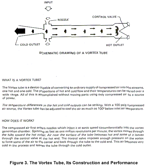
The Vortex Tube. The Vortex Tube (for cooling or heating) is another available method of worker temperature control (See Figure 3). The Vortex Tube is a very simple device. It is a tube of approximately 1/2 to 1 inch diameter and perhaps 6 to 12 inches in length. The Vortex tube is simple, lightweight, and inexpensive. Air is admitted into the side of the tube and split into two separate airstreams, each exiting at opposite ends of the tube. One airstream is hot, the other is cold. Either of these two airstreams may be directed into the worker's disposable suit or hood to provide external temperature control to the worker.
The only disadvantage of the Vortex tube is that it uses a comparatively high volume of air, approximately 15 to 20 cfm per worker. Compared to the air used by a pressure-demand type respirator, each vortex tube will use as much air as would be needed to supply 4 or 5 pressure demand respirators. Therefore, the use of vortex worker cooling will increase the size and cost of both the compressor and the breathing air purifier.
Adiabatic Cooling. Adiabatic cooling is available when sufficient cooling capacity has been designed into each of the multistage compression steps found internally in the high pressure compressor. Provided that the high pressure compressor cooling design is adequate, cool or ambient temperature air will be produced at the high pressure compressor outlet. This air is carried into the in-line air reserve tanks and then into the asbestos work area via high pressure lines to an air control panel. The air pressure regulator on this panel reduces the high pressure air from pressures of 1000 to 4000 psig down to the required respirator line pressure (typically in the 65 to 100 psig range). The air temperature also drops dramatically with this air expansion at the control panel and the resulting cold air is directed into the respirator lines at the panel.
Figure
2.
Typical Installation of Low Pressure Breathing Air System
Figure 3. The Vortex Tube, its Construction and Performance
Adiabatic cooling is very simple, lightweight, and reliable provided the compressor has been initially designed to be adequate for such cooling.
In the typical asbestos worksite, cold breathing air will aid in cooling the asbestos worker. Normal external body cooling methods have been reduced due to the previously described working conditions, while body core cooling effects of breathing cool air have not been changed. Cooling methods using cool or cold breathing air can also be used incidentally to provide cool air externally to the worker. This can be accomplished simply by directing the cool exhaust from the respirator exhalation valve down inside the asbestos worker's disposable garment. Workers generally are observed to accomplish this added cooling without special instruction or added personal equipment. With a high pressure breathing air system, a single user of a pressure demand full facepiece type respirator (with built-in adiabatic cooling) may use a total of only 4 standard cubic feet per minute (SCFM).
When asbestos abatement is accomplished in extremely cold environments, there may be a need to provide heat to the breathing air. Heat exchangers with a warm water heat source can be used to heat and control the breathing air being delivered to the respirator hoses. Supplemental heating or cooling may be used with any type breathing air system.
(4) Continuous Carbon Monoxide (CO) Monitor and Alarm
Providing a continuous CO monitor and alarm is a requirement of law and of common sense. Carbon monoxide monitors and alarms are available from many sources. A list of sources is included in Part V of this Appendix. The CO monitor should be purchased as a part of the overall breathing air system or breathing air purifier assembly. Proper choice of CO monitor and correct installation in the system are aided by the system manufacturer. Since CO monitor and alarm systems can malfunction, employers may find it prudent to install two such systems to ensure continued protection in case of failure.
Manufacturers of carbon monoxide monitors have available two basic types of sensors. One sensor type is specific or sensitive only to carbon monoxide. This sensor will ignore all other trace chemicals and alarm only in the presence of CO. The monitors based on a CO-specific sensor are usually more expensive. The other type of sensor also will alarm in the presence of carbon monoxide, but it is a non-specific sensor and may also give alarms in the presence of trace chemicals when carbon monoxide is not actually present. Non-specific systems are usually less expensive.
Some manufacturers tend to recommend the non-specific type sensor for inclusion in the asbestos removal air system. Non-specific sensors may give more alarms. The reasoning behind recommending the non-specific type is that other potentially harmful chemicals are being detected when this system gives such an alarm. For instance, off-gassing of certain synthetic compressor lubricants not recommended for use as lubricants in breathing air compressors may cause such non-CO alarms. The breathing air system would be protected against an "unfamiliar'' rental compressor in which such adverse synthetic lubricants had been used by the action of such alarms.
On the other hand, the occurrence of numerous alarms will disrupt the asbestos worksite and could significantly increase the cost of removal or make job completion difficult. Such excessive alarms also create a "cry wolf" attitude in the workforce, leading to a disregard for the alarm. Disregard for the CO alarm is a very dangerous practice and MUST be avoided. Therefore, the CO monitor must be kept in calibration and all alarms equally respected. Immediate air quality samples may be taken during the alarm to verify the absence or presence of CO. Should numerous alarms be experienced, the possible sources for other chemicals being detected by the alarm should be found and eliminated.
If CO alarms continue after efforts at finding a local fix, contact the CO monitor manufacturer for aid. In this case, consider with the manufacturer or supplier of the carbon monoxide monitor either (1) obtaining a new CO monitor of the same type, to eliminate the possibility of a mechanically or electrically alarm, or (2) obtaining a CO monitor and alarm from a different manufacturer.
IF A LOW PRESSURE BREATHING AIR SYSTEM IS BEING USED WHEN THE ALARM SOUNDS:
When the alarm sounds, the breathing air system should immediately be switched to the high pressure standby air reserve system. Depending on the capacity of the reserve system, the workers should exit the toxic removal zone. Typically, one 220 standard cubic foot tank will provide one man equipped with a 4.0 SCFM pressure-demand respirator with fifty-five minutes of escape time.
The outside supervisors should check and make certain all workers are exiting. All respirators should be accounted for and verified as no longer in use.
With sufficient high pressure reserve or when using a high pressure breathing air system with sufficient in-line reserve capacity, CO alarms and unexpected compressor shutdown can often be handled without disruptions in the asbestos removal work.
Remember, air being processed in a low pressure air system is almost immediately being delivered to and breathed by the workers. Therefore, when using the low pressure system, there is an immediate need for switchover to the high-pressure reserve air when the CO alarm sounds. If only the minimum high pressure reserve is available, the workers should exit the area. If additional reserve air capacity is available, the workers should exit when the reserve supply approaches the minimum acceptable amount.
When using a high pressure breathing air system with an in-line high pressure air storage bank, the compressed air from the compressor is delayed and diluted by the action of the in-line storage bank before being delivered to the workers. When the CO alarm sounds in a high pressure breathing air system, the stored air at the moment of the alarm has previously been processed through the CO monitor, and is already guaranteed to be Grade D quality. The air in the in-line air bank therefore remains available for the workers' continued use.
IF A HIGH PRESSURE BREATHING AIR SYSTEM IS BEING USED WHEN THE ALARM SOUNDS:
Immediately stop the air flow from the compressor into the in-line reserve air bank by shutting the output air valve. [Note: If so arranged, this step may be automatically accomplished through relays in the CO monitor.]
Immediately provide a gas sample test for CO in the supply output from the air bank to the workers. (See discussion of the gas detection method which follows).
If the sample test shows no carbon monoxide in the air from the air bank going to the workers, then the workers may continue to work. They may work as long as no further air from the compressor is being admitted into the air bank, and provided more air time is stored in the bank than the required one hour reserve time. When and if the one hour reserve level is reached, the workers should be removed.
A study of formation of carbon monoxide in breathing air compressors was done by Lawrence Livermore Laboratory in 1978*. Two separate conclusions from this study which are of particular significance for breathing air systems used in asbestos removal are as follows:
- "Exhaust gases from combustion engines are the major threat to the quality of compressed air.'' (p. 6)
- "The preceding observations [of the study] indicate that a high temperature shut-off or alarm, as one of the options specified by OSHA, does not significantly protect against CO contamination of compressed air. In the event of local overheating in a compressor, the effectiveness of a temperature sensor would depend on its placement near the hot spot. The oil reservoir, because of its much lower temperature, is unreliable as an indicator of overheating. Therefore, a high-temperature alarm or shut-off device should not be considered as a substitute for CO monitoring." (p. 7)
Gas Detector Tubes. As previously noted, when a CO alarm sounds in a high pressure system, a gas sample test for CO in the supply output from the air back to workers should be done immediately. Whether a low pressure or a high pressure breathing air system is in use, after all workers have exited, and all respirators have been accounted for, air testing should be conducted to determine if CO was present or not.
Although direct reading CO monitors are available, a less expensive and simple to use on-site air analysis method can be used to provide a positive backup analysis method in case a CO alarm is activated. This method uses preset chemical color change analysis. The analysis chemicals are precharged and sealed into small glass tubes. Different tubes are available for many different gases. A small case contains several sets of tubes and the constant volume sampling pump. Other tubes useful on an asbestos jobsite include those which indicate oxygen and carbon dioxide. These tubes are simple to use. The ends are broken off a tube and the tube is inserted into the pump. Operating the hand pump draws a measured volume of air sample through the tube. The results are read directly on a scale on the tube.
Practice samples taken on two known CO sources can be used to verify the detection of CO using detector tubes. Cigarette smoke can be used as a common type of low-level carbon monoxide sample test. Exhaust from an idling, non-catalytic-equipped automobile, truck, or other engine is a second example, this time of high CO content. Taking these two known CO-content samples on a CO tube will educate the crew as to what the abnormal CO reading actually looks like on the tube. The usual CO sample results on a high quality breathing air is zero CO.
Periodic gas tube sampling results should be permanently logged. This provides an additional record of the air quality on the job site.
There are three (3) general types of breathing air systems potentially available for use in asbestos removal. These general types are categorized according to the pressure levels at which they are designed to operate:
- the low pressure system
- the high pressure system
- high pressure pre-pumped tanks
The typical low pressure system is shown in Figure 2. This system consists of:
- a low pressure compressor
- an aftercooler assembly with water removal traps
- an air purifier assembly
- a standby high pressure air reserve assembly
- a surge-tank or in-line air volume tank
- a distribution hose and distribution manifold with connections for respirator hose lines.
(a) A Low Pressure Breathing Air Compressor
The low pressure breathing air compressor produces pressures between 100 and 200 psi. It has sufficient flow capacity to provide the flow needed for the respirators being used. The compressor should also be equipped with sufficient interstage and aftercooling capacity to reduce the air temperature to within 1 OF of the ambient air temperature. The low pressure compressor should be equipped with suitable moisture removal traps to tee able to remove 60% to 85% of the water/oil condensed within the machine. Water removal may be either automatic and continuous or manual and periodic.
(b) An Aftercooler Assembly with Water Remove/ Traps
The aftercooler assembly is used immediately following the low pressure breathing air compressor. The aftercooler and its water trap may be incorporated physically in the compressor. The purpose of the aftercooler assembly is to guarantee that the air temperature is reduced to within 1 OF of ambient air temperature. Such a reduction in temperature forces condensation of water/oil in the airstream. The cyclone-type water separator or water trap is also a part of the aftercooler. This separator or water trap is used to allow removal of the water/oil mixtures condensed by the action of the aftercooler in the airstream.
After coolers may either be ambient air-cooled or water-cooled. Ambient air aftercoolers will not function as well on the hottest days, when the most worker cooling is needed. Water-cooled aftercoolers may work best on the low pressure system.
(c) An Air Purifier Assembly
The purpose of this purifier network (see Figure 4) is to polish the air to at least the required Grade D air quality.
The air inlet is on the upper left of the diagram. The air path is actually downward into the prefilter, a rid the first active element encountered by the al r is an added water coalescing element in the down tubes and bottom of this prefilter. Water is mechanically collected on this coalescing section of the prefilter and drains downward into the water removal trap. Water can be drained automatically or through a manual valve added to the bottom of this trap.
[IMPORTANT NOTE: ALL CONDENSED WATER AND OIL MUST BE DRAINED AND REMOVED FROM THE AIR ADMITTED INTO THIS PREFILTER. If proper reduction of air temperature and proper removal of condensate is not accomplished at the entrance to the prefilter, the breathing air purifier may not function as well as expected and may require more filter replacements.]
The air continues moving upward through the prefilter and into the oil removal section of the prefilter. At the lowest visual level in the prefilter there is a red color-match band. Oil vapors are adsorbed by the filter media, beginning just above the red band. Oil adsorption causes a red color change in the originally white filter material above the red color-match band. As additional air quantities are passed through the prefilter, this color change will progress upward inside the prefilter material as the filter material adsorbs the oil from the air stream. When the color change approaches the top of the prefilter material, the prefilter should be changed. The above description is typical of the visual or color-change method of notice of need for filter change, which is used by several manufacturers in many types of adsorption filters.
[IMPORTANT NOTE: Some low pressure compressors that may be available for local rental may be built and set up to power industrial machines. Industrial machines such as air tools. jack-hammers, roadwork earth drills. and other such machines have very different requirements from a compressor required to produce breathing air. Industrial machines may require a high oil content in the air stream. Industrial oiling requirements may be designed to be met directly in the compressor output or may be met by the addition of airline oilers. In such cases where a high oil content is found in the air, the solution is to either remove airline oilers downstream of the compressor outlet, or change to a different and suitable compressor that has low oil output.]
Figure 4. Typical Low Pressure Breathing Air Purifier Assembly
Air processed through the active prefilter passes into the dual dryer tower assembly, into the air-switching plumbing circuit assembly. This air-switching circuit simply directs the air into the heatless air dryer assembly. There are two of these drying towers. Each tower is alternately either on-line, drying the air, or off-line being regenerated.
The regeneration of the off-duty tower is accomplished by taking a percentage of the dry air from the output of the on-duty drying tower and running it in a reverse direction through the off-duty tower. The dew point of the drying air and also the amount of air to be diverted to drying the off cycle tower is determined by the setting of the regeneration pressure gauge.
The breathing air purifier shown in Figure 4 has visual moisture indicators in each drying tower. These indicators change color in the presence of moisture. Observation of these color-change indicators allows the operator to observe the functioning of the drying operation. During operation the on-cycle tower will begin to absorb water. After approximately 2~/2 minutes the system will switch, the now dry off-cycle tower will become the functioning tower, and the on-cycle tower will go over to off-cycle as it begins to be de-adsorbed or regenerated.
Over a period of years in normal operation the ability of the towers to be regenerated decreases. Calorimetric indicators are available to indicate when the absorber material in these towers must be replaced.
[IMPORTANT NOTE: The drying action of these towers depends on water adsorption and water de-adsorption. If the system is operated with a depleted prefilter, oil may be passed into the drying towers. The activated alumina in the drying towers will adsorb oil and therefore will provide a backup to the function of oil removal normally accomplished by the prefilter. However, oil adsorbed in the drying towers will not be desorbed in the towers. Therefore oil passing through a saturated prefilter will effectively ruin the water drying function of part or all of the tower and result in shorter-than-expected drying media lifetime and more frequent tower media replacement.]
Air from the dryer towers now enters the CO catalyst. This catalyst changes harmful CO to CO2. The catalyst can process up to 400 ppm inlet CO and still keep the output air below the required 20 ppm limit.
[Note: A carbon monoxide continuous monitor and alarm is required on all breathing air systems used in asbestos removal work, even if a CO catalyst is also used.]
Periodic replacement of the CO catalyst is recommended by all purifier manufacturers
Air now flows to the final absorber canister where odors are removed by activated charcoal. This canister is usually replaced on a recommended interval basis. This final canister may also contain a particle filter which prevents adsorber particles from passing downstream.
The low pressure breathing air compressor plus the described breathing air purifier is time proven and will deliver high quality breathing air.
(d) A Standby High Pressure Reserve System
The only effective method to store sufficient air for an industrial sized asbestos removal work crew is through the use of high pressure storage tanks. Such tanks are available for rental at low rates, and they can be delivered directly to the asbestos abatement worksite.
The standby reserve system functions by sensing both the line air pressure and the air quality provided by the compressor and breathing air system. Should the compressor fail and the line air pressure begin to drop or should CO levels exceed 20 ppm, the standby reserve sensing system detects dropping pressure or presence of CO and starts to supply pressure from the reserve air system. This pressure supply is automatic and immediate, and functions to continuously provide sufficient air to operate the respirators.
There are two operational notes that must be included in the startup and shutdown checklist for the operator of this system:
On Startup of the Low Pressure Breathing Air System:
(1 ) Start the low pressure breathing air compressor and verify air delivery at full pressure.
(2) Only then turn each reserve air tank on.
On Shutdown after workers have exited:
(1 ) Turn OFF each reserve air tank valve.
(2) Only then go through the procedures to shut down the breathing air compressor.
Operating any standby reserve air system without including the directions listed above could cause inadvertent loss of air from the reserve system. This could result in low or zero reserve air in the standby reserve air tanks when it is really needed.
(e) A Surge Tank or In-line Air Volume Tank
A surge tank provides air storage capacity so that peak flow conditions will not deplete the air supply.
(f) A Distribution Hose and Manifold with Connections for Respirator Hose Lines
Once air is processed through the low pressure air purifier it is directed into the delivery air line and is immediately available to the worker.
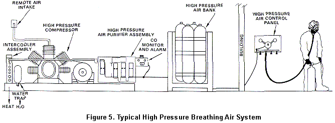
The high pressure breathing air system (Figure 5) is composed of four major components:
(a) a high pressure compressor
(b) an air purifier assembly
(c) a high pressure air storage bank
(d) a high pressure control and distribution panel
(a) A High Pressure Compressor
The function of the high pressure compressor is the same as that in the low pressure system. The low pressure compressor utilized one or two successive compression steps or stages to compress the air up to 100 to 200 psi. The high pressure machine pumps the air to pressures of 2000 to 4000 psi utilizing from 3 to 5 successive stages of compression.
Each time the air is processed through a
compression stage, its density and its pressure are increased, and its volume is
decreased. The air temperature increases sharply through each compression stage due to the
adiabatic process. Following each stage of compression, the air is put through an
intercooler that transfers considerable heat out of the air. Once the compressed air
temperature is brought down, it cannot hold the moisture that it carried before that stage
of compression, and the water vapor and other vapors condense. Following each intercooler
stage is a cyclone-type liquid trap. The liquid trap is a vertical cylinder with a drain
valve in the bottom. The air is introduced tangentially near the top of the trap, and
creates a spinning vortex within the trap. The higher density condensed liquids are thrown
against the cylinder walls of the trap. They drain down along the walls of the trap and
can be removed from the compressor through the drain valve in the bottom. Even though
water has been condensed and removed, the air is saturated. In this state, further
compression or cooling will be able to remove additional water. This will be done in the
following stages.
Figure 5. Typical High Pressure Breathing Air System.
The air from the preceding compressor stage is now carried into the intake of the next compressor state. Here it is again compressed, cooled, and water is again extracted. This process of compression, cooling, and condensate removal is repeated for every succeeding state within the high pressure compressor. High pressure makes it possible to take out considerably more heat from the air than could be extracted by low pressure compression. The same is true for moisture removal within the high pressure machine. It is capable of removing much more of the water vapor that was originally being carried by the air than if the air were only compressed to a lower pressure in a single or dual state compressor.
Heat and water removal inside the compressor, by intercoolers and drain traps, is done by mechanical methods. Mechanical removal methods are more or less permanent removal methods. These methods do not require replacement absorber cartridges nor the maintenance associated with such cartridge changes. Very high percentages of condensates are capable of being mechanically removed in high pressure processing. The result of such processing is to reduce the water vapor and other contaminants that must be removed by the following absorber purifier.
Therefore, one of the major effects of high pressure mechanical processing in the breathing air compressor is to reduce the required size and weight of adsorbent material needed in the following high pressure purifier assembly.
(b) The Air Purifier Assembly
The high pressure purifier assembly is made up of an aftercooler, a combination coalescing filter/drain trap, and a number of successive purifier containers that hold adsorber materials.
The function of the aftercooler is similar to that of the intercoolers. Following the aftercooler, the air is put through a combination mechanical coalescing filter element/drain trap. Vapor is not removed in mechanical drain traps. There are some very tiny drops of condensed materials, called aerosols (water, oil, etc.) which act almost like vapor and also move through ordinary drain traps. In order to mechanically remove these aerosols, they are forced, in the coalescing element, to impact or squeeze together and to form big drops out of the aerosols. These coalesced liquid drops can now be drained from the air stream.
The air now moves into the absorber section of the purifier.
Adsorber materials to be used in high pressure absorber chambers are the same as used in low pressure designs:
molecular sieves
silica gel
activated alumina (Al2O3)
activated charcoal.
At this point the engineer or designer of the high pressure purifier assembly has two major advantages over designing for low pressure air purification: (1 ) more condensate and contaminates have already been mechanically removed within the high pressure compressor section, and (2) the density of the air is much higher. Higher density air means that any given amount of adsorber will be more effective and will process more air. Both of these facts add to a reduction in the required adsorber needed.
There is a third factor in the overall high pressure design which also allows for a reduction in the required adsorber material. One major action of the in-line high pressure storage bank is to allow a smaller compressor to be used. The high-pressure in-line air bank allows the designer to reduce compressor output, size, weight, and horsepower. Therefore overall cost of this system is reduced. Costs for the high pressure system are lower both in initial purchase and in operating costs, than if the designer were operating without the in-line high pressure air storage bank.
The combination of:
- more condensate mechanically removed by the high pressure compressor
- increased adsorber effectiveness due to higher density of air
- lower air flow rates needed because of the combination of the high pressure compressor and in-line air storage bank
make possible the use of simpler, smaller, and less costly adsorber purifiers to process the high pressure air.
As with low pressure breathing air systems. high pressure regenerative adsorber systems are available, but their high initial cost make them unattractive to the engineer/designer. They are generally not included in high pressure assemblies processing breathing air for asbestos work crews.
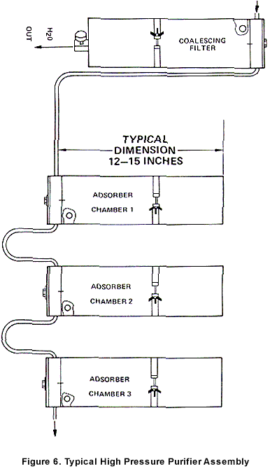
Following the coalescing filter trap, there are usually two (2) to four (4) successive additional disposable adsorber containers. These are usually replaced on a machine time basis, but color change or other indicators are available. Since cartridges cannot regenerate themselves it is especially important that they are changed on a regular and scheduled basis. Failure to do so could allow desiccants to reach saturation and permit contaminants to enter and contaminate the high pressure storage bank system. A typical high pressure purifier assembly, consisting of an inlet coalescing drain trap and three successive replaceable adsorber containers, is shown in Figure 6.
Continuous CO Monitor and Alarm. Air passing from the high pressure purifier should be continuously monitored by an electric carbon monoxide alarm. Should any carbon monoxide be produced in the compressor or induced into the compressor air intake, it will be detected by the CO monitor. The CO alarm will visually and/or audibly warn if the CO level goes above 20 ppm. Visual warning is accomplished by meter and by a green/red system of lights. High decibel audible alarms are also available.
CO monitors can be adjusted to alarm at different levels of CO present. In order to meet the requirements of ''Grade D'' air, no more than 20 ppm are allowed.
(c) The High Pressure In-line Air Storage Bank
High quality air, Grade D or better, is now pumped directly into the high pressure storage bank. The function of this high pressure storage bank is to act as an air reservoir, so that:
- the peak air flow demands can be met without concern for or limitation by the maximum compressor output
- the compressor and purifier can be sized for lower flow rates than the peak flow rates required
- in emergency compressor conditions, such as power failure, compressor stoppage, etc. the work crew air supply remains uninterrupted for at least one hour
- greater capacity (typically three to six hours) than the minimum required for escape (one hour) can be used to allow routine or emergency maintenance of the system to be accomplished without interrupting the work crew.
Figure 6. Typical High Pressure Purifier Assembly
Air Reservoir for Peak Flow. A compressor pumping directly to a large work crew is analogous to a water pump pumping without a water reservoir. The direct supply water pump must be sized to meet the peak flow demands. Water systems include a water storage reservoir so that the peak flows are supplied by the reservoir, while the water pump operates over longer periods of lower flow to maintain the reservoir level. This pump/storage design method is done more than just for convenience; it is done also for cost reasons. Even small community water systems would require prohibitively sized water pumps, if only direct supply from the water pump was used. Therefore the function of large storage capacities is included in all municipal water systems. We see large water tanks located strategically around cities.
Air Reservoir to Lower Costs. Air storage is different from storage of water. Water density is the same for all water pumps, while air density is a function of air pressure. Low pressures simply do not have enough density to store air effectively. Therefore low pressure air compressors must deliver and use the air almost immediately, since no effective storage is available. Higher pressure increases air density. Increased air density makes possible the compressor/ storage combination which can more effectively accomplish the air supply to large crews. Therefore smaller, lighter weight, lower horsepower and lower cost high pressure air compressors can compress air into and maintain the high pressure reservoir. The high pressure reservoir can supply peak flow rates without being limited by lower maximum compressor flow rates.
The major reason for the use of in-line high pressure air storage is economic. The in-line high pressure air storage bank allows a lower cost of smaller high pressure compressor to provide breathing air to a large asbestos removal work crew. Without the in-line air storage bank, a larger and more costly air compressor and larger and more costly air purifier assembly would be needed to support the same crew.
Reserve air time in excess of one to one and a half hours is also available from the high pressure system. Extra time above the one hour escape time may be called the working reserve. Working reserve time, stored in a high pressure storage bank, is very valuable in that unscheduled or scheduled maintenance can be done without interrupting the work crew.
Air Reservoir for Emergency Conditions. The working reserve allows the severity of emergency conditions to be lessened. For instance, an inadvertent compressor stoppage with a low pressure system requires an immediate switchover to the high pressure air reserve. A normally open air valve is held closed until switchover is required to provide adequate egress time. The reserve air tanks must be fully charged. It is recommended that a low pressure sensor and alarm be used to monitor the standby reserve. In the high pressure system with in-line storage and reserve, the worker does not enter the toxic zone in the first place unless he is drawing air from the reserve air bank. Both outside and inside toxic zone pressure gauges show at all times the number of hours of reserve time for any crew size. Should the power fail and the high pressure compressor stop, there is no requirement for a switch to operate in order for the ''reserve air" to be brought on line.
The working reserve also decreases the severity of the other conditions which might constitute real emergency conditions in other systems. For instance, consider that the CO alarm sounds. The CO alarm has auxiliary relays which can be used in the high pressure system to protect the air previously stored in the air bank. (Likewise, such relays can switch the low pressure system over to the reserve air bank.) It does this by providing power to close the air valve on the compressor output (high pressure system) or open the air valve to the backup reserve bottles (low pressure system). At the first moment of alarm, this valve is shut. Also, for both high and low pressure systems, manual valving on the compressor output can be used to shut off flow upon CO alarm. With Grade D air stored in the air bank, there is no CO emergency for the inside workers. The outside supervisors and outside workers can deal with this alarm as a potential CO problem. The inside workers are using the previously processed air stored in the bank, which will supply them for the next several hours. The problem can be identified and the condition corrected.
(d) A High Pressure Control and Distribution Panel
Air is delivered into the toxic zone from the high pressure air bank through small high pressure lines. These lines may be flexible or solid high pressure lines and may be several hundred feet in length. This high pressure line is led into the building to a lightweight air control and air distribution panel. The panel has a high pressure gauge that may be marked off in pressure units or it may be rated in time units (hours) for any size work crew. Each worker attached by respirator hose to this panel can at all times see exactly how much working reserve time (and escape time) is available.
As with the low pressure breathing air system manifold, this panel also contains a regulator and low pressure gauge. The regulator sets, controls and maintains the respirator hose-line pressure to a precise value. Momentary fluctuations in the low pressure hose lines are removed by the action of the regulator. The regulator holds the respirator hose-line pressure at a constant value, which allows for more consistent respirator performance.
Respirator low pressure hose-line lengths are still limited to not more than 300 feet.
Filling SCBA Tanks. If equipped with filling devices, high pressure SCBA tanks can be filled from any part of a high pressure system.
Worker Cooling with the High Pressure Breathing Air System. Providing worker cooling is a consistent problem in asbestos removal work. Both the high and low pressure breathing air systems have built-in worker cooling. Because of its higher working pressures, high pressure cooling is more noticeable. The air supplied to the air panel is at high pressure and is also at ambient temperature (2000 to 4000 psi and about 70� - BEEF). The air panel regulator reduces this pressure to 80 to 100 psi. When this pressure reduction takes place, the air temperature drops 25� to 40�F or more. This cold low pressure air is supplied to the respirator hose lines. These hose lines may moderate the air temperature somewhat, but the result is that very desirable cold air is available for the worker to breathe. This adiabatic method of cooling is reliable, lightweight, and requires no added heat exchanger or other worker or work area equipment. It does not increase airflow requirements, and adds no cooling air burden to the compressor designer's air supply requirements.
(3) High Pressure Pre-Pumped Tanks
Sufficient breathing air for small jobs may be supplied by using pre-pumped high pressure air. There are two different choices of supply:
- rental cylinders from commercial specialty gas suppliers (This is the same source used to provide the high pressure standby air reserve.)
- the pre-pumped in-line reserve air bank from a high pressure breathing air system.
Either of these air sources can supply a small crew of one to four workers with enough air for one to three days. Operating in this manner, no electrical, gasoline, or diesel power is required at the jobsite. The pre-pumped air has already been processed through a CO monitor; therefore, jobsite monitoring is not required. Special designs of larger air storage banks are possible so that this simple method of operation can be extended for larger crews and for longer times. A single high pressure air source located either at a major job site or at home base can function effectively to support one or more additional off-site jobs.
(4) Other
The Non-Lubricated Compressor. There are certain models of industrial-crew sized compressors which use solid state lubrication, rather than liquid lubrication. These machines, if recommended by the manufacturer, can be used to pump air for human consumption. Most of these special machines are more expensive than their oil-lubricated equivalents. They generally have to be rebuilt with less running time than the oil lubricated models.
The majority of breathing air around the world is pumped from oil-lubricated machines, and purif- ied to Grade D air using the absorber technology described in this report. Whether high or low pressure air, whether commercial divers, sport divers, industrial plant breathing apparatus, fire and rescue crews, all use Grade D air produced from adsorption-based air purifiers.
Unless there is a very special reason, and unless the extra cost can be justified, there is no need to operate the special class of non-lubricated compressor.
The Ambient Air Pump. The ambient air pump is a low power (1/2 h.p. to 5 h.p.) pump. These pumps take ambient air and supply it to the respirator through the appropriate hose line. They are not intended to improve the quality of the air being pumped.
Ambient air pumps provide an output air pressure in a range from 8 psig to 30 psig. They do not provide sufficient pressure to operate any currently approved NIOSH/MSHA pressure-demand combination SAR/SCBA respirator. Therefore, ambient air pumps cannot be used with the respirator recommended by NIOSH for use in asbestos abatement operations.
(5) Use of Breathing Air Systems in Multi-story Buildings
Large and heavy breathing air system components, including the compressor, the air purification system, and the reserve air tanks, are best located on ground or basement floor levels. The lightweight components, such as the feed air lines and air distribution manifolds or air panels, are all that is necessary to install at upper floor levels.
The respirator manufacturers' specified pressure for the respirators being used must be maintained at all times at the inlet to the respirator hose. The Occupational Safety and Health Administration (OSHA) and NIOSH regulations prohibit the actual hose length to exceed 300 feet in length.
The simplest method to provide the manufacturer-specified pressure on the upper floor level is to provide a ground level compressor with output pressure sufficiently higher than the pressure required by the respirator, and use a control regulator on the respirator manifold. Highest compressor output pressures will achieve satisfactory performance at the highest floor level.
III. CAUTIONS IN THE USE OF BREATHING AIR SYSTEMS
1. Gross contaminations of the inlet air to the air compressor will adversely affect purifier performance. Therefore,
CAUTION: The compressor intake should be properly located to intake ordinary uncontaminated ambient air.
2. Inlet air must not be oxygen deficient. No breathing air system will increase the oxygen content of the intake air being processed. Therefore,
CAUTION: The compressor intake should be located to ensure that air with normal ambient air oxygen content (19.5% - 23.5%) is always available.
3. The inlet to the compressor should be located away from known or mobile (transient) sources of carbon monoxide. That is, it should be located away from and protected from the engine exhaust of any diesel or gavel line drive compressor, or away from the exhaust from automobiles, trucks, lawnmowers, and other mobile (transient) internal combustion engines. Therefore,
CAUTION: The compressor intake should be remotely located from the compress all possible mobile exhausts to ensure that carbon monoxide (CO) is excluded from the intake. The intake should be remotely plumbed to a safe position at each worksite.
4. The potential for carbon monoxide poisoning through the intake of the compressor of the breathing air system is high enough so that further protection from carbon monoxide is required by OSHA regulation. Such additional CO protection should be part of any breathing air system at any asbestos removal worksite.
The General Industry OSHA Safety and Health Standards (29 CFR 1910.134), states ''If an oil lubricated compressor is used, it shall have a high-temperature or carbon monoxide alarm, or both. If only a high-temperature alarm is used, the air from the compressor shall be frequently tested for carbon monoxide to insure that it meets the specifications."
Since the asbestos removal workplace is usually a temporary worksite, the expectation is that mobile sources of carbon monoxide may pose more hazard than in a permanent worksite. If carbon monoxide is introduced into the intake it will NOT be detected by a high temperature alarm. Therefore, due to the conditions at the asbestos removal worksite, the recommendation is made that additional protection from carbon monoxide be provided by a continuous carbon monoxide monitor with alarm. This choice of a continuous carbon monoxide monitor and alarm is the preferred choice rather than using a high temperature alarm on the compressor.
Catalysts that under ideal conditions can cause oxidation of carbon monoxide to the less dangerous carbon dioxide (CO2) are a feature to help protect against carbon monoxide in breathing air. However, OSHA requires the protection of a monitor and alarm against CO in the breathing air. Therefore,
CAUTION: A continuous carbon monoxide monitor and alarm should be installed and functioning in the compressor output breathing air stream,
5. When operating a diesel or gasoline driven compressor, addition precautions should be taken to plumb both compressor intake and exhaust away from the compressor and into a safe location. Therefore,
CAUTION: Any internal combustion engine-driven compressor should also have the exhaust line plumbed to a safe location, as well as having the intake line plumbed to a safe (separate) location.
6. An open-ended or broken pneumatic line or hose may create a hose ''"hipping'' or moving hose hazard. Therefore all pneumatic lines, low or high pressure, should be restrained. Simple and inexpensive restraints such as sandbags are usually sufficient. Therefore,
CAUTION: Air supply hose or lines should be restrained every 15 feet of their length. (This does not include the length of hose from the distribution manifold to the respirator. )
7. Asbestos removal worksites create the possible hazard of airborne toxic fibers. Therefore standard practices to contain these fibers must be used. The compressor is a concentrator of any airborne contaminants. The compressor intake inlet and the entire length of intake hose should be free of airborne asbestos fiber contamination. Therefore,
CAUTION: The compressor intake point and intake hose should never be operated in air contaminated with asbestos fibers. The compressor and air intake hose should be located in a clean air environment outside the asbestos work zone.
8. Compressor oil suitable for use in breathing air applications should be used. The only proper source for such oil type recommendation is the manufacturer of the breathing air compressor or breathing air system. Therefore,
CAUTION: Use only compressor oil suitable for use in breathing air applications.
and
CAUTION: The recommendation for oil suitable for use in compressors for breathing air applications should only be made by the compressor or breathing air system manufacturer.
9. The user of any breathing air system should recognize the importance of running the system at the correct design conditions. The heat, moisture and oil removal abilities designed within the compressor are important. If the high air temperatures generated by compression are not reduced, the water/oil vapors will not be condensed and therefore may pass through the water traps without being removed. This circumstance may present an overload of water/oil to any breathing air purification assembly that follows the compressor and aftercooler. Such purifier assembly overload will cause the adsorber assemblies within the purifier assembly to be replaced on a more frequent than normal schedule. Unnecessary canister replacement increases the expense of maintaining the breathing air purifier. Therefore,
CAUTION: Compressors equipped with breathing air purifier assemblies should be used. Breathing air purifier assemblies should be used as designed and not overloaded.
10. Pure oxygen gas must not be pumped by or utilized in a breathing air system for use with air supplied respirators. Only air is pumped by these systems. Pure oxygen gas is never to be used in the standby escape time or reserve air system. Only compressed air is used in the standby reserve air system. Pure oxygen is not to be supplied from any source into the respirator systems used in asbestos removal. Therefore,
CAUTION: Never use pure oxygen gas in any part of the gas supply system supplying the air supplied respirators. Respirators are supplied only with Grade D air.
11. High pressure air reserve bottles are, and all compressed air systems have, pressurized vessels. Therefore, an explosive hazard potential exists.
CAUTION: Before starting and operating a compressor and purifier system, inspect all system components for structural damage which could result in an explosion. Inspect safety relief valves carefully. and verify that they are in good working order.
IV. COST ANALYSIS COMBINATION SUPPLIED AIR VERSUS A.R-PURIFYING RESPIRATOR SYSTEMS
This part of the Appendix presents an analysis of the comparative cost of equipping equal sized crews with combination supplied air respirator/breathing air systems versus air-purifying respirators.
Some important conclusions of this cost comparison, which follows in detail are:
- A breathing air supply system used with pressure-demand, combination supplied air respirators, is considerably lower in cost than an air-purifying respirator system.
- The initial cost of outfitting an asbestos removal crew is lower when equipped with air purifying respirators than the initial cost of obtaining a breathing air system and equipping the same crew with pressure demand combination supplied air respirators.
- The yearly cost for the asbestos removal crew equipped with air-purifying respirators is much higher than the same size crew equipped with the breathing air system and combination supplied air respirators. This higher yearly cost is the result of the recurring daily costs of the required replacement filters for the air-purifying respirators.
- The higher initial cost of the pressure-demand combination supplied air respirators and breathing air system over the cost of the air-purifying respirators is usually returned to the owner of the breathing air system within only 6 months to one year of operational use.
- Following this short time of operational use, the pressure-demand combination supplied air respirators with the breathing systems continue to save the owner the cost of the entire system approximately every 6 months to one year throughout its subsequent operational lifetime.
*Based on the average yearly cost of $20,509.00 of the Supplied Air System.
RESULTS COMPARATIVE INITIAL COSTS
Crew Size 15 Workers All Cases
| I. Initial cost full facepiece PAPR-HEPA |
8,985.00 |
| II. Initial cost full facepiece negative pressure |
1,425.00 |
| III. Initial cost breathing air system with pressure demand combination respirators |
26,000.00 to 38,000.00 |
[NOTE: Low pressure rental breathing air compressors have not been calculated; however, they are sometimes locally available. If rental compressors were calculated. it would reduce the initial purchase cost and increase the yearly costs of the low pressure breathing air system in this comparative study. High pressure breathing air compressors are not generally available for rent.]
RESULTS COMPARATIVE YEARLY COSTS
| I. Full facepiece positive pressure air purifying powered air high efficiency particulate filtration respirator (PAPR -H EPA) |
$57,030.00 to $6110,168.00/yr. |
| II. Full facepiece negative pressure air purifying respirator |
$30,617.00 to $60,617.00/yr. |
| III. Breathing air system with full facepiece pressure demand combination respirators |
$18,709.00 to $22,309.00/yr. |
Conclusion:
On a yearly cost basis, breathing air systems cost considerably less than air purifying replaceable filter respirators. The higher yearly costs of the replaceable filter air purifying respirators are due almost entirely to the recurring daily costs of replacement filter canisters.
COSTS OF FULL FACEPIECE POSITIVE PRESSURE DEMAND AIR-PURIFYING HIGH EFFICIENCY PARTICULATE FILTER TYPE RESPIRATORS (PAPR-HEPA)
Initial Purchase:
| 15 each PAPR-HEPA at $599.00 each | $8,985.00 |
| Yearly cost: |
|
|
Amortize in three years |
$2,995.00/yr. |
| Unscheduled maintenance at 10% per year | 898.00/yr. |
|
|
53,137.00/yr. to 106,275.00/yr. |
|
TOTAL COSTS YEARLY |
$57,030.00 to $110,168.00 |
[NOTE: Inclusion of the air purifying respirator types in this comparative cost study should not be inferred as a recommendation for their suitability for use in any given asbestos removal circumstance. Breathing air systems, either low pressure (1 00 to 200 psi) or high pressure (2000 psi or more), used with pressure-demand full-facepiece respirators, or pressure-demand self-contained breathing apparatus provide higher levels of protection and the high reliability needed for asbestos removal.]
COSTS OF FULL FACEPIECE NEGATIVE PRESSURE AIR-PURIFYING RESPIRATORS
Initial purchase:
| 15 each negative pressure full facepiece respirators at $95.00 |
$1,425.00 |
Yearly cost:
| Amortize in three years | $475.00/yr. |
| Unscheduled maintenance at 10% per year | 142.00/yr |
| Scheduled maintenance for daily replacement of filter canisters averaging either $8.00 or $16.00 per man per day for 250 days |
30,000.00/yr. to 60,000.00/yr. |
| TOTAL COSTS YEARLY |
$30,617.00 to $60,617.00 |
[NOTE: Inclusion of the air purifying respirator types in this comparative cost study should not be inferred as a recommendation for their suitability for use in any given asbestos removal circumstance. Breathing air systems, either low pressure (1 00 to 200 psi) or high pressure (2000 psi or more), used with pressure-demand full-facepiece respirators, or pressure-demand self-contained breathing apparatus provide higher levels of protection and the high reliability needed for asbestos removal.]
COST OF BREATHING AIR
SYSTEM WITH FULL FACEPIECE COMBINATION PRESSURE DEMAND RESPIRATORS
Initial purchase:
| Breathing air compressor | $8,000.00 TO $12,000.00 |
| Air purifier system |
$9,000.00 to $17,000.00 |
| 15 each combination respirators complete with fittings and hoses at $600.00 each |
$9,000.00 |
Yearly costs:
| Cost of compressor operation at 21�/100 SCFM | $6,623.00/yr.* |
| Purge air costs at 21�/1000 SCFM | $1,325.00/yr.* |
| Amortize breathing air system in five years | $3,400.00 to $5,800.00/yr. |
| Unscheduled maintenance at 10% per year | $2,598.00 to $3,798.00/yr. |
| Scheduled maintenance for breathing air purifying canister replacement* (see below) |
$1,763.00/yr. |
| Amortize respirators three years | $3,000.00/yr. |
| TOTAL COSTS YEARLY: |
$18,709.00/yr. to $22,309.00/yr |
*Scheduled maintenance:
| Oil purifier prefilter 6x per year at $60.00 - $80.00 | $480.00/yr. |
| Al203 dryer towers 1x every 3 years at $100.00 | $33.00/yr. |
| CO catalyst filter 1x per year at $750.00 - $1,800.00 | $1,800.00/yr. |
| Odor removal charcoal filter 2x per year at $90.00 - $120.00 |
$240.00/yr. |
| Total scheduled maintenance per year |
$1,763.00/yr. |
*The cost figures given above represent "worst case" estimates because they are based on 24-hour day, 365-day year operations (8760 hours/yr.). Actual costs will be proportionately less depending upon actual use.
V. SUPPLIERS OF BREATHING AIR EQUIPMENT
INCLUDING SUPPLIERS
OF
High and Low Pressure Breathing Air Compressors
High and Low Pressure Breathing Air Purifiers
Carbon Monoxide Monitors
Gas Detection Tubes
Heat Exchangers
Particle Filters
Vortex Tubes
|
American Bristol Industries Asbestos Control Technology Atlas Copco Turbonetics Bauer Consumer Fuels, Inc. Control Resource Systems, Inc. Critical Services, Inc. Daboco, Inc. Davey Compressor Company Deltech Engineering, Inc. Dynamation, Inc. Dynatech Frontier, Inc. E. D. Bullard Co. Enmet Corporation Hankison Corporation
|
Industrial Pump & Compressor Industrial Safety Products Ingersol Rand Joy Manufacturing Company Mine Safety Appliances Company National Draeger North Safety Equipment Racal Airstream Inc. Rhine Air, Inc. Rix Industries Sullair Corporation 3M Company Vortec Corporation Willson Safety Products |
Return to NIOSH Guide Table of Contents
*Formation of Carbon Monoxide in Air Compressors, Lawrence Livermore Laboratory, T.M. Distler, July 26, 1978, 94550 Contract No. W-7405-Eng-48 Back to Document